The heart of the solar thermal testing lab is the performance testing. Most of the testing requirements come from the ISO 9806-1,2, 3 standard.
A testing lab is interesting because the standard of testing may define exact pieces of equipment and procedures. The standard, describes the conditions to be created, the data to be collected, its precision and accuracy, and what to report. The exact equipment and procedures are not dictated, but you are audited to verify you are producing what the standard requires, however you actually choose to do it.
ISO 9806 defines flow and temperature to be provided, requires measurement of solar radiation, wind, and so on; ISO 9806 tells how well to measure, but we decided how, specifically, and with what instruments the testing woudl be performed.
We chose to use National Instruments Real Time hardware and LabVIEW software for data acquisition and control. Much of our testing equipment was bespoke construction that we designed and built ourselves.
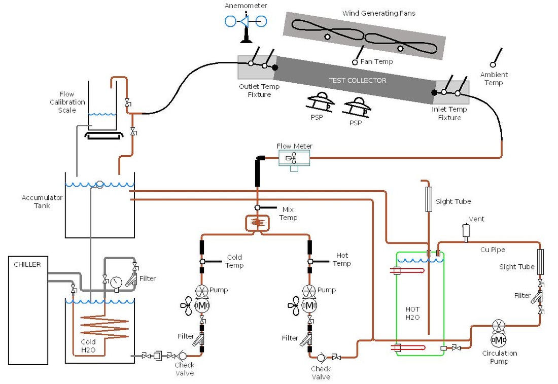
Image 1. Schematic of the flow system.
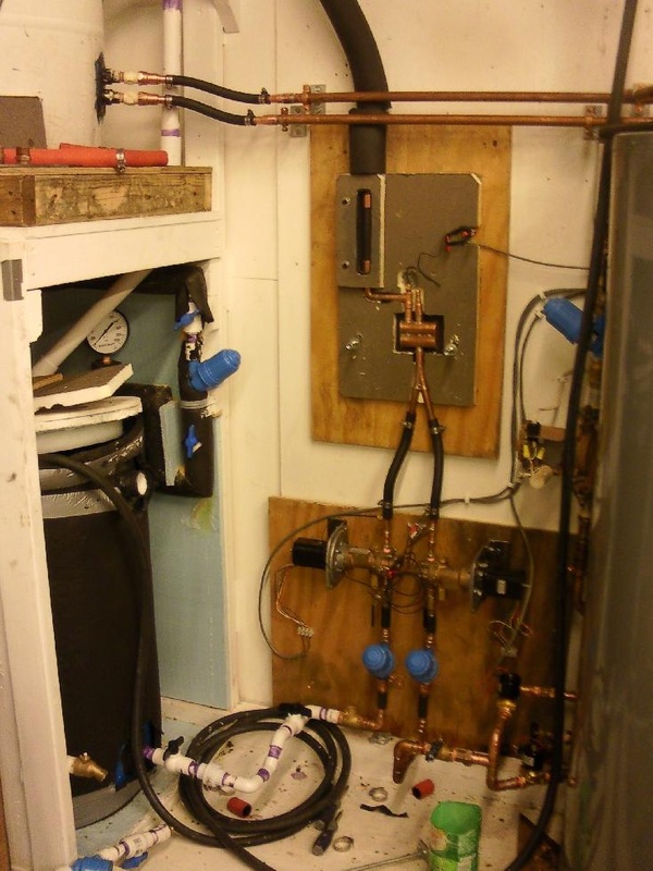
Image 2
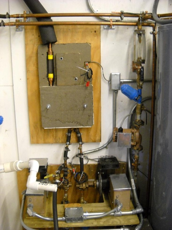
Image 3
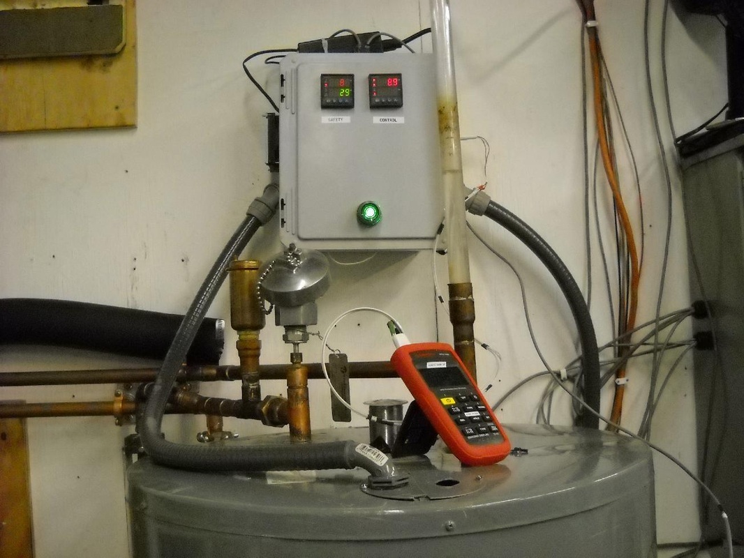
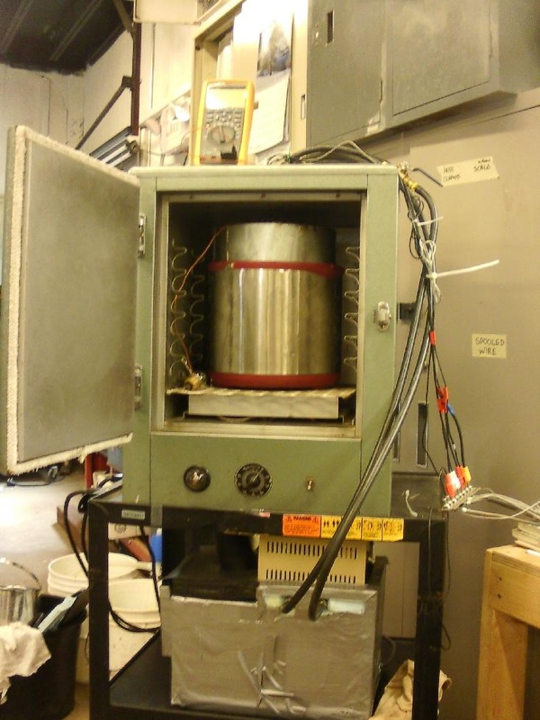
Image 4. Hot tank controller and safety system
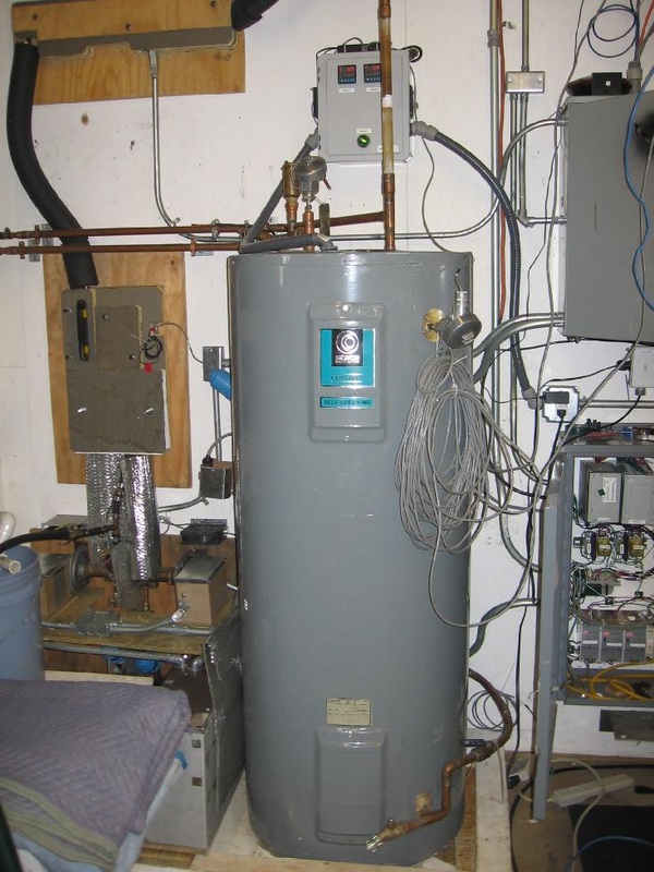
Image 5. The hot tank flanked by the flow system and the data cabinets. Flow meter is seen above.
|
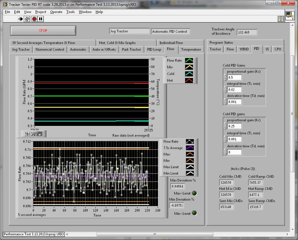
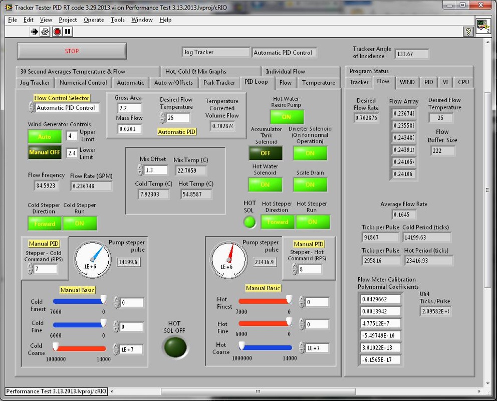
Performance testing of solar collectors for certification and rating requires precise and accurate control of the heat transfer fluid with regards to mass flow rate and temperature.
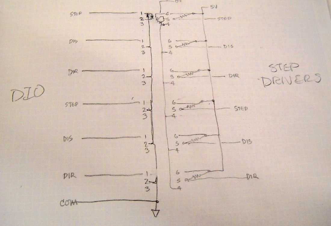
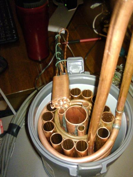
The temperatures must vary from near freezing of water 5°C to 95°C. The temperature at the inlet to the collector must be held within ±0.1°C for long periods of time. The mass flow rate must also vary quite a lot, but at a given rate it cannot not vary more than ±1%. Many similar labs had implemented large tanks of stable water, but this supply could run out if the test took a long time, and changing from one temperature to another was time consuming. We decided it would be possible to build an actively controlled system implementing two pumps one for a hot supply and another for a cold supply and mix them by varying pump speed to produce the range of temperature, and flow with the desired accuracy. We used National Instruments cRIO Real Time hardware, and LabVIEW software programming of the FPGA to run a fast PID control system. We learned a great deal putting this together. Producing a flow accurate to a fraction of 0.1°C is difficult. One thing we would do differently now is buy accurate Coriolis Flow Meter or other accurate fluid flow measuring instruments. We were able to do this well with our less expensive equipment, but we spent a great deal of time sorting it out. Image 2. Assembling the flow system. Below are two pump motor combinations with filters and valves. They mix together in a copper mixing chamber. Thermistors measure the cold and hot temps entering the mix chamber, and another measures the mixed outflow. Above, out of sight, is a flow meter for volume flow. Image 3. The pump motor drivers are shown in place and in the junction box between them is a bespoke optical isolation circuit. Below is the bespoke motor power supply. We had difficulty with the electrical noise of the stepper motors interfering with flow meter readings. We had to reconfigure the power supply, wiring, and add the isolation circuits to get noise free accurate readings. Image 4. We adapted a hot water tank to run unpressurized and near boiling. This required assembly a purpose built temperature control system with safety cut off relay. One controller cut power on over temperature conditions, the other manages tank temperature. Screen shots of the performance test control and acquisition software
An example of roll your own solutions:we needed to add optical isolation to the stepper motor drive system for the flow due to the electrical noise of the steppers would interfere with flow meter measurement.
These are part of the precision thermistor and RTD calibration system that had to be constructed to improve differential temperature measurement.
|