            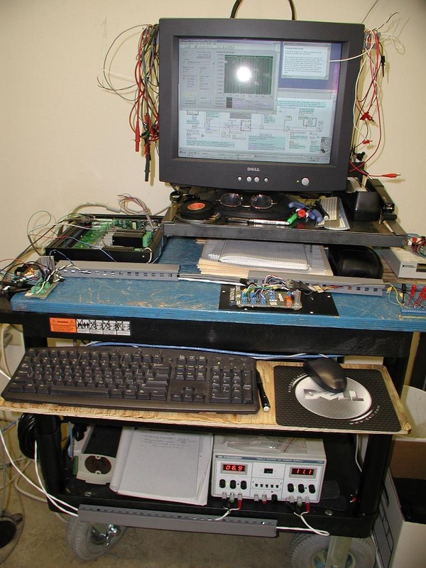
This is the early data acquisition setup for testing cam and crank position sensors. It is portable and made from available supplies to eliminate some red tape.
National Instruments data acquisition and control hardware was used, and LabVIEW programming language. Later a database was developed to allow searching among the numerous test runs results.
|
This cam sensor turns up on a lot of vehicles, cars, trucks, Ford, Mercury, etc.
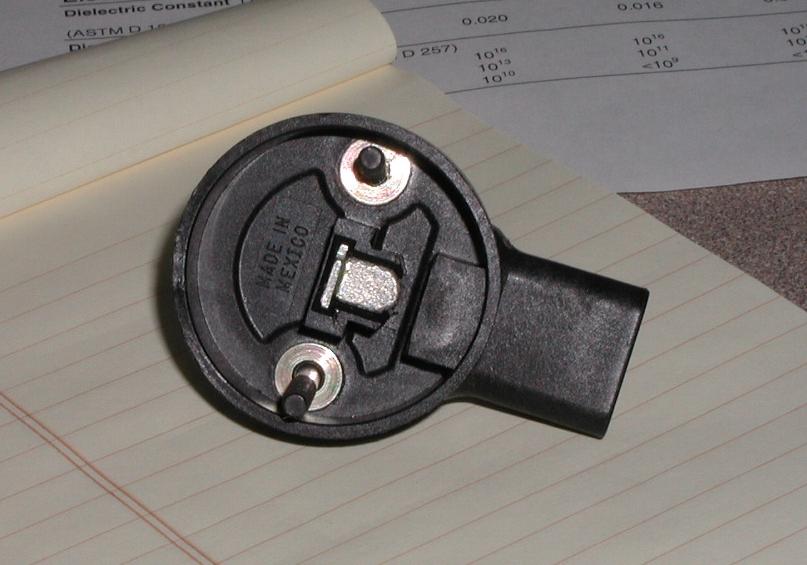
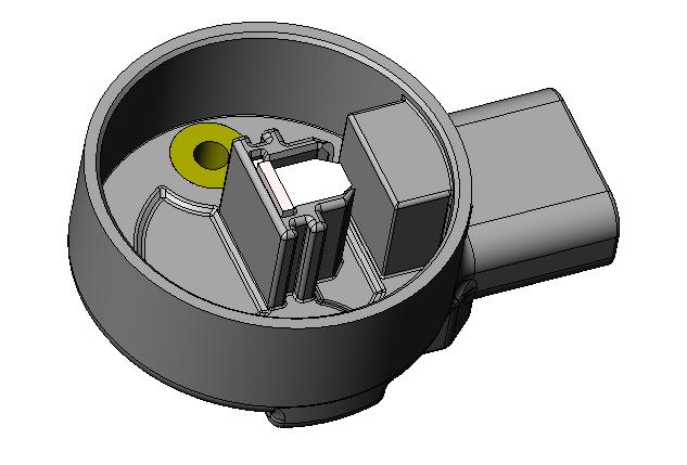
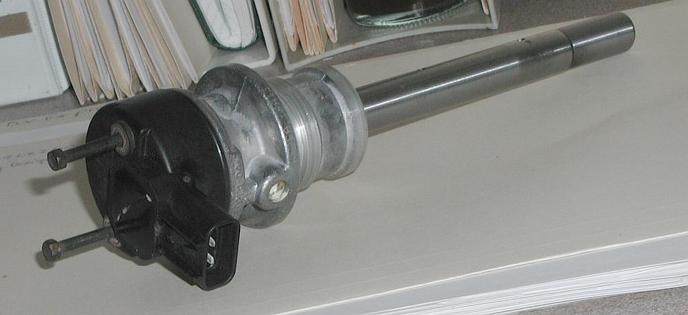
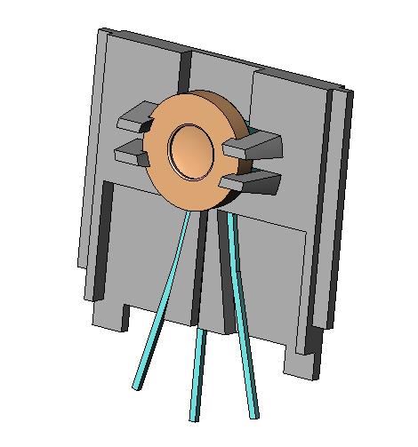
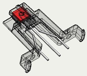
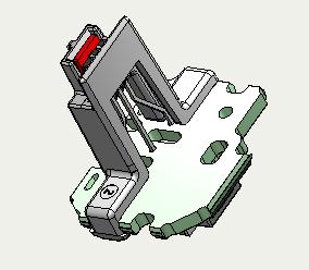
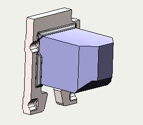
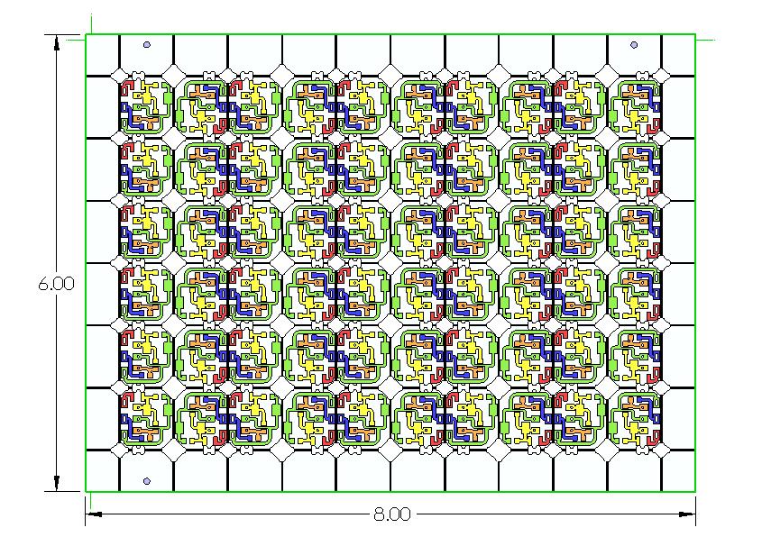
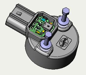
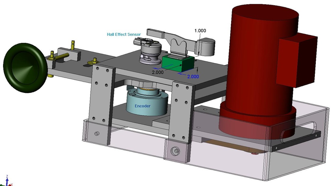
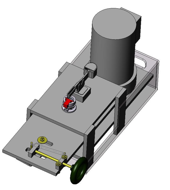
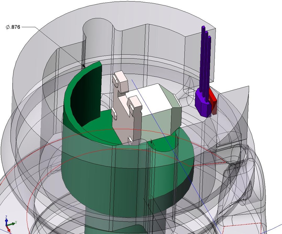
The cam position sensor signal is effective even if it is far from correct because it merely reports whether the number one cylinder is on the power stroke or not. 1st in the gallery is an OEM sensor with the alnico magnet revealed underneath. 2nd is a 3D CAD representation of the aftermarket part. 3rd is the sensor mounted on its rotor and housing which is driven by the camshaft. 4th shows how the steel flux guide is captured to the Hall Effect IC in the OEM version for insertion into the cavity of the sensor housing. The 5th and 6th views show the new design. There is an overhang that traps the IC in place and the square steel flux guide slides in behind and is held by friction. The IC and flux guide holding fixture clips to the circuit board so that handling is much easier until the IC is soldered to the PCB. The original desing wis very fiddly and falls apart during handling. The 7th image shows the magnet and mounting plate/flux guide soldered together. View 8 is the layout of printed circuits which are scored to break off individual boards. The 9th view is a top view with the printed circuit revealed.in place and the captured screws in their compression limiting inserts are in place beneath the washers. The 10th shows a rapid prototype in the lab test apparatus. A set of OEM parts were characterized and then the prototypes tested against their average baseline response. The 10th and 11th images show CAD views of the test apparatus I don't have a good photograph of the actual machine. The 12th image shows the elements of the magnetic circuit that provides the sensor output. A stamped steel plate is soldered to the alnico magnet which is trapped by interference in the plastic housing. The plate also acts as a flux guide and concentrator, amplifying the flux density. The steel flux guide pressed against the Hall IC concentrates the flux through the active area of the IC. This guiding of the flux allows a larger air gap for the target wheel to spin through, and less mechanical accuracy is needed. Not shown is the conditioning fixture through which each assembled and magnetized sensor is passed. Alnico magnets can drift down as much as 10% in flux density from temperature cycling. By saturating the magnets fully then knocking them down by passing between two powerful neodymium magnets, this 10% excess, that would be lost to heat cycling, is eliminated and the magnets are stable over their life. The magnets were specified specifically with this step in mind. The data acquisition was handled by a PC with a National Instruments E-Series board installed. On the left in the image is a signal conditioning accessory. Below is the power supply. The LabVIEW software made it simple to graphically show how each sensor differed from the OEM baseline average performance. On earlier projects the data was placed in an Excel file, but later on a MySQL database was establish to enhance the ability to find, compare, and analyze test results. |