     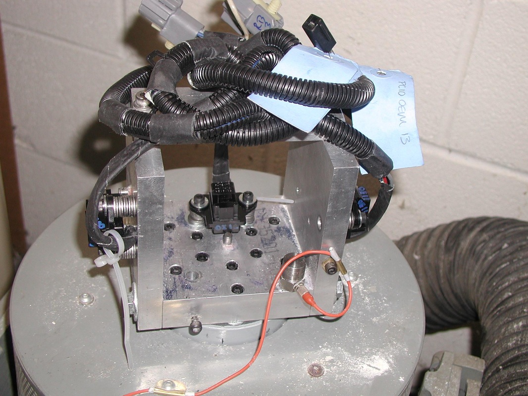    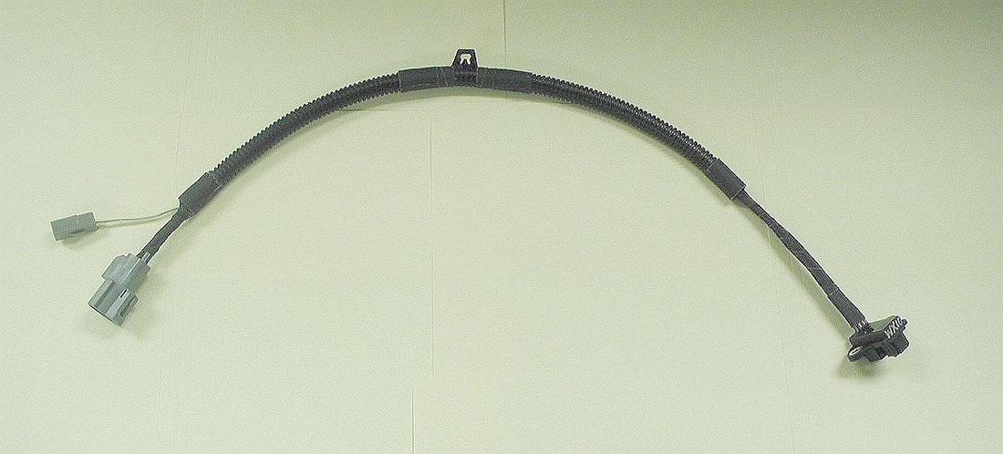   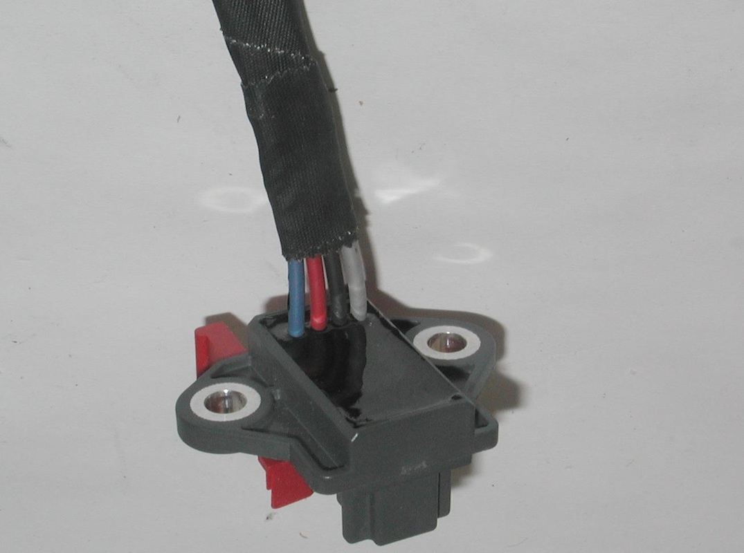
The finished crank sensor assembly.
|
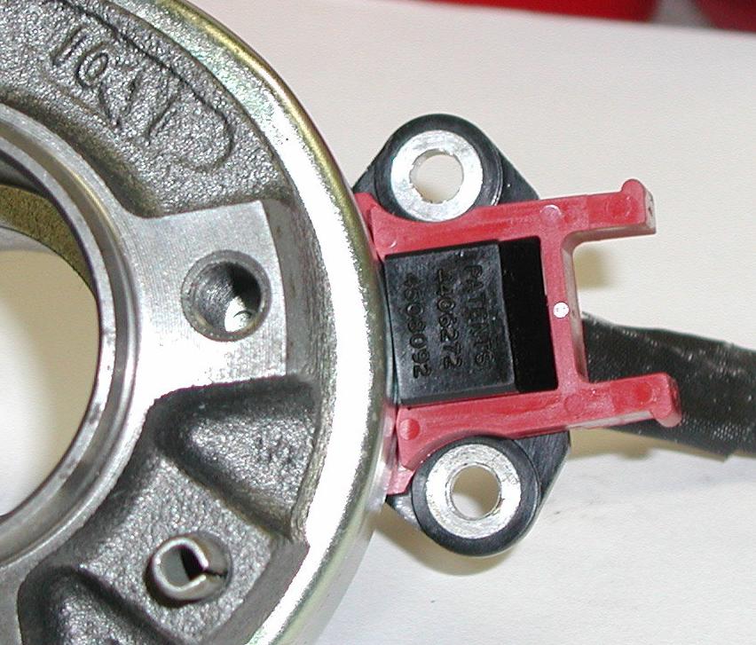
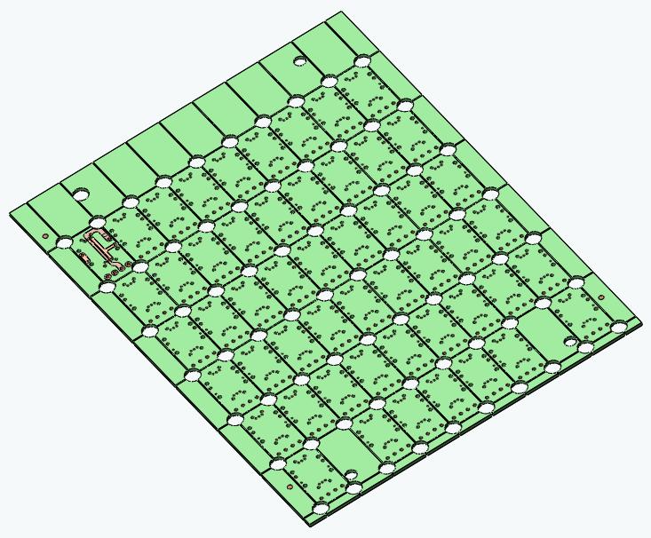
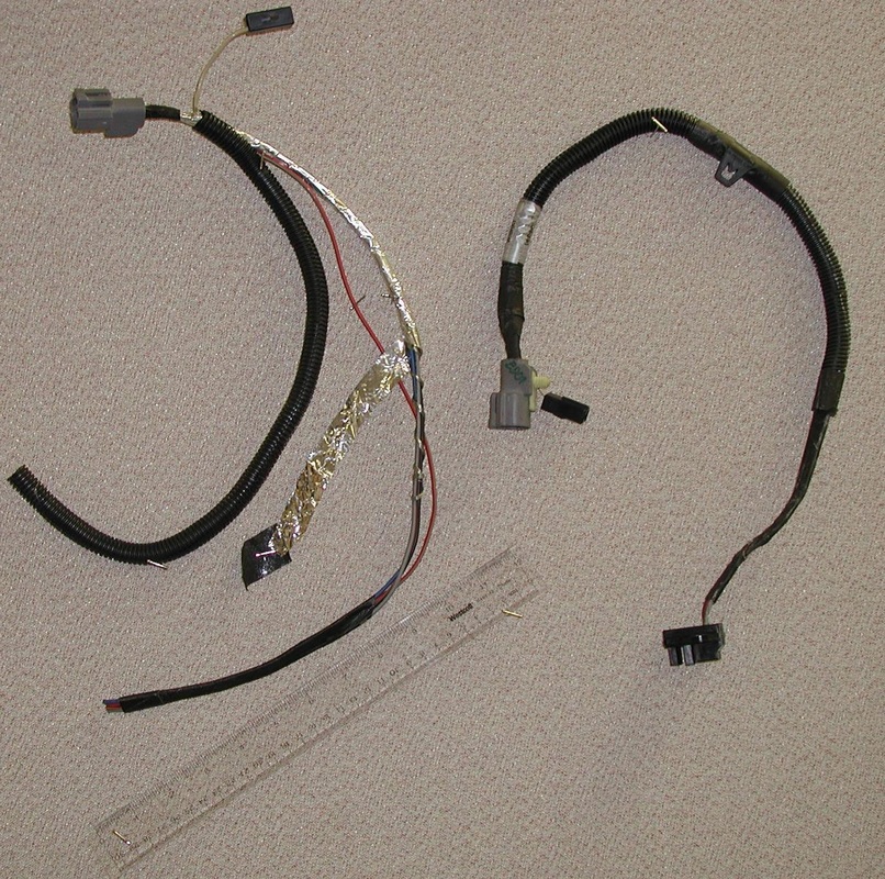
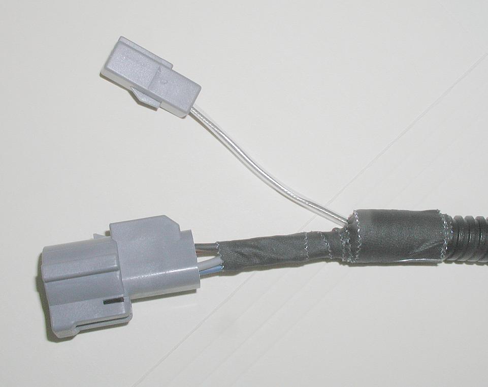
Aftermarket Ford Crankshaft Position Sensor
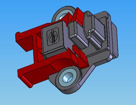
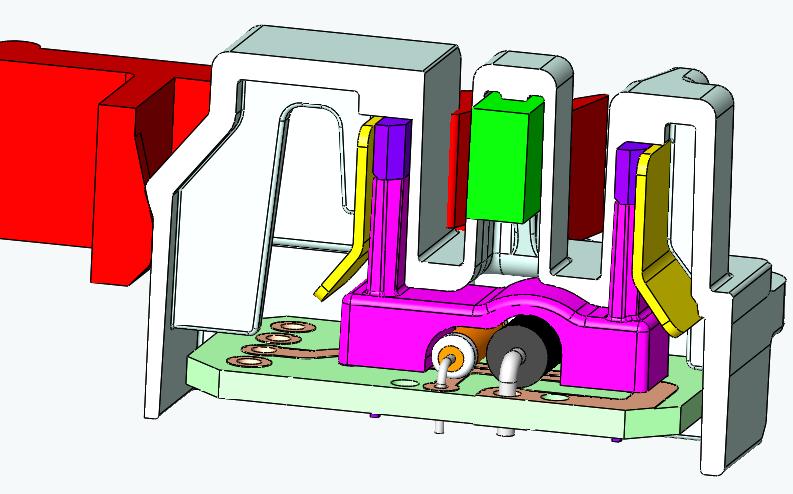
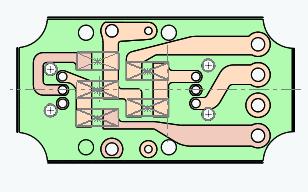
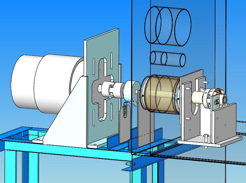
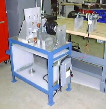
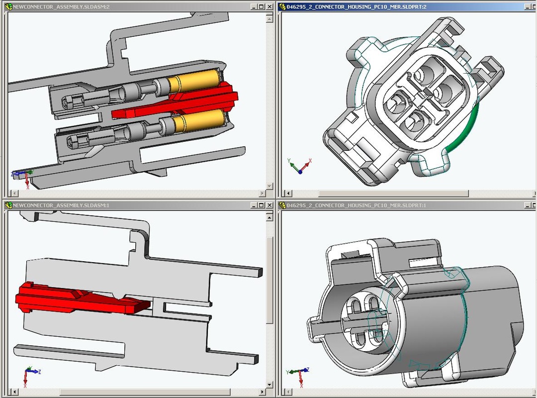
This older Hall Effect Sensor by Ford is a well designed part, but it is labor intensive to make. Ford was charging SMP a lot to buy this; we were able to make the part for about 16% of that cost. Even though the volume was relatively low, the savings were great. We combined some of the assembly line with production of a GM sensor to further reduce the capital expense. We could industrialize sensors like this in about 18 months. We were able to make some improvements that improved manufacturability. This is always trick with aftermarket parts - if it doesn't look like the OEM, it invariably causes returns for no reason, often our hindsight offers many functional and quality improvements that change the appearance too much to be acceptable. For example, the exterior plastic part of the OEM is not designed to the best plastic part design principles. I got away with radiusing the visible edges to improve the molding process and provide more dimensional stability due to reduced warping. Also the interior had more coring out and radiusing than the OEM part. In particular, the OEM harness was hand made with hand wrapped shielding and a drain wire and connector. We sourced a very nice custom cable that is better in every way. We had to put corrugated tubing around it to make it look like the OEM part, but the custom cable itself is much better having a molded outer sheathing. Duplicating the look of the OEM required some careful tape wrapping that is totally unnecessary with the new design. Internally, we created a Ryton (high temperature plastic) fixture to improve assembly of the circuit assembly. We used pick and place and reflow soldering of surface mount components. After the soldered circuits were broken out from their array, the fixture is clipped to the circuit board. The Hall Effect ICs with die bent leads are clipped into the fixture to ease assembly to the circuit board. After assembly the parts are all held in place securely so they do not shift or fall out when the board it turned over for soldering of the Hall IC leads to the board. On the design side, the dual Hall ICs are placed off from the poles of the centrally located magnet. Stamped steel flux guides increase the flux density at the small sensing areas of the ICs. The guides are bent to provide lead-in, easing the pressing home of the PCB assembly. The Samarium Cobalt magnet is a quality choice, but many more powerful Neodymium Iron Boron magnets are common in later years. The SmCo magnets are not a powerful and so the air gap between the Hall ICs and the magnet is not very large. THis means the Target wheel that spins in the air gaps has to be positioned very well. Ford developed an installation tool (red plastic) that is clipped onto the sensor so that it is bolted down in the proper position relative to the target wheel. Another complication of Hall Effect sensors is that magnets can't conveniently be purchased in a magnetized state. They stick together powerfully, and attract any ferromagnetic dust and filings which are largely impossible to clean. The polarity matters and orienting the magnets for proper assembly is tricky. The manufacturer demagnetizes and cleans them for shipping. A magnetizing fixture is required to charge the magnets after assembly. A final test of function is required and a sophisticated custom test machine was developed. LabVIEW programming and National Instruments hardware was used. This allowed the addition of analysis functions for trouble shooting and statistical process control after the line was up and running. |